ARM Firmware Reverse Engineering

Hello everyone. In this blog we continue with Firmware Reverse Engineering. We will dive into Bare Metal Reversing. If you remember, in our previous topic, we analyzed the firmware of TP-LINK Archer AX 21 V4.6 in 2024. Here, we will take things a little further.
I have a Nucleo F030R8 board (with ARM Cortex M0 processor) and I wanted to use it for Firmware Reverse Engineering. What we will do in this blog is to simply program the board and then reverse the firmware and reinstall it on the board. Let’s think typically like hacking an IoT board but with a simpler scenario:
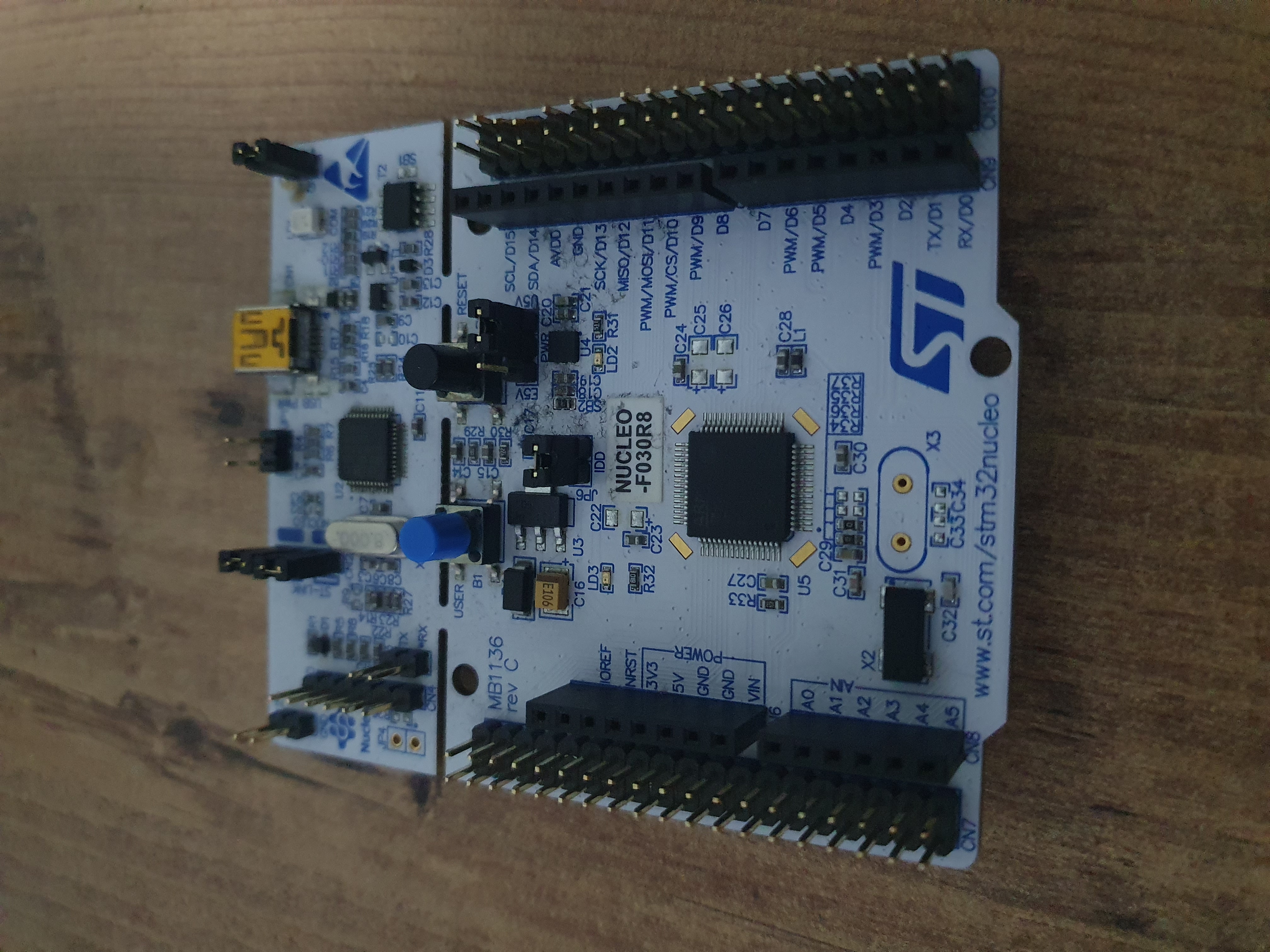
This is the card I have. If you have a different board of nucleo, you can follow the steps in this blog.
Obviously, I have not developed myself in microcontroller coding, but during this concept process, we will develop ourselves both in microcontroller coding and firmware reverse engineering.
The necessary programs will be CubeIde, CubeProgrammer and Ghidra. With CubeIde we will do the programming for our board, with Ghidra we will reverse the firmware and in the last step we will load the firmware that we reverse with CubeProgrammer on our board.
Coding
The coding we will do is completely simple. The Nucleo F030R8 board has a User Button (you can take a look at the blue button in the photo) and a Green led (LD2). We will coding that lights the Green Led when the button is pressed, then we will reverse the firmware with using Ghidra.
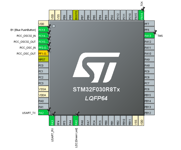
After creating the project in CubeIDE, we can focus on the .ioc file. Since we will work with the button and led on the board, as you can see from the photo, the adjustments have already been made by the IDE. So there is nothing extra to do here. From my card, User Button is on PC13 and Led2 is on PA5.
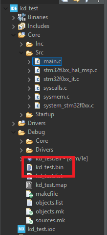
Before we start coding, we will need to make a small adjustment to the project we have created. Since we will analyze the firmware, we will need to get the .bin file by loading the program on the card:
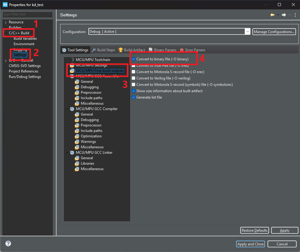
Right click on the project and select Properties. Then go to C/C++ Build > Settings > MCU/MPU Post Build Outputs and enable Convert to binary file (-O binary) option. Now, in the Project Explorer tab on the far left of the IDE, go to Core > Src > main.c project. This is our main project.
Before coding in main.c, we can take a look at the MX_GPIO_Init function. This function contains the configuration of the pins prepared by the IDE:
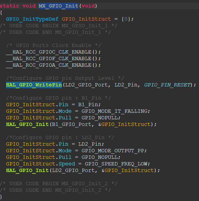
As it can be seen, the User Button for the F030R8 board is set to B1_Pin (GPIO_PIN_13) as GPIOA and GPIOA and LD2_PIN (GPIO_PIN_5) for LED2. If you are on a different board you can check these settings.
Now let’s return to the main function and start coding:
  /* USER CODE BEGIN 2 */
  uint8_t ButtonStatus = 0;
  while (1)
  {
	  ButtonStatus = HAL_GPIO_ReadPin(B1_GPIO_Port, B1_Pin);
	  if (ButtonStatus == 0) {
		  HAL_GPIO_WritePin(LD2_GPIO_Port, LD2_Pin, SET);
	  }
	  HAL_GPIO_WritePin(LD2_GPIO_Port, LD2_Pin, RESET);
  }
The code is really simple. Now Let’s take a look at the codes one by one:
ButtonStatus = HAL_GPIO_ReadPin(B1_GPIO_Port, B1_Pin);Firstly, we use the HAL_GPIO_ReadPin function in the while section of main. This function is used to read the state of the corresponding pin and takes two parameters. The first parameter specifies the GPIO port where the pin is located. In STM32 microcontrollers, GPIO pins are connected to specific ports (A, B, C, etc.). There are, for example, GPIOA, GPIOB, GPIOC, etc. This parameter is used to specify which port the pin is located on. In our code, we specify that it is GPIOA. The second parameter specifies the GPIO pin you want to read. Each port can have more than one pin on it (for example, port A has PA0, PA1, PA2, etc.). This parameter specifies which pin you want to read the status of. In our code, we specify that it is B1_Pin, GPIO_PIN_13.
Finally, the return address of this function is passed to the ButtonStatus variable of type uint8_t. So, this function reads the status on the specified pin and passes the result to the ButtonStatus variable.
if (ButtonStatus == 0) {
    HAL_GPIO_WritePin(LD2_GPIO_Port, LD2_Pin, SET);
}
HAL_GPIO_WritePin(LD2_GPIO_Port, LD2_Pin, RESET);
After the pin reading, we make an if comparison. If the value assigned to ButtonStatus is zero, it lights the led. If the ButtonStatus value is 0, it means that the Button is pressed. If it is 1, it means that the Button is not pressed.
The first parameter of the function - HAL_GPIO_WritePin - specifies which GPIO port to use as previously described and I specified it as GPIOA in our code. The second parameter specifies the GPIO pin to be set or reset and I gave the LD2_PIN variable with the defined value GPIO_PIN_5. Finally, the third parameter specifies the state of the pin.
If the button is not pressed, we still use the HAL_GPIO_WritePin function but the last parameter is specified as RESET. This sets the corresponding pin to 0 when the button is not pressed. Thus, the led will not light up when the button is not pressed.
Now let’s load this code on our board and see the result:
As it seems, our board is running perfect. As soon as I click on the button, the green LED lights up. Now let’s go back to Ghidra and start analyzing the .bin file. The generated .bin file will be under the Debug file:
Firmware Reversing
Let’s select our .bin file by clicking File > Import File in Ghidra, but do not close the screen that appears directly, we will need to make important adjustments.
First of all, let’s start by setting the Languages section and search for ARM in the filter field:
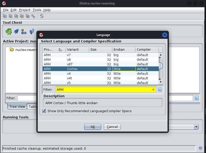
I chose Cortex 32-bit, Little Endian as the Language. If you have the same board, choose this option, if you have different boards, choose the language according to your board. Then you can exit this Language tab by saying OK.
Then let’s click on Options from the same screen and the setting we will make here is really important. Here we will make adjustments such as Base Address.
First we will need to set the base address. **But how can we find the Base Address of a firmware? The best method would be to look at the memory map of the device.
We are working on an ARM based board. We can find the Base Address through Nucleo’s datasheets:
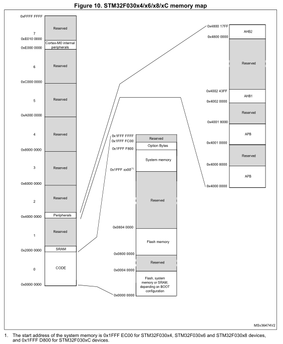
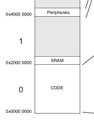
The photo above is the memory map of the STM32F030x4/x6/x6/x8/xC boards. Since my board is among these devices, I will need to make use of this memory map:
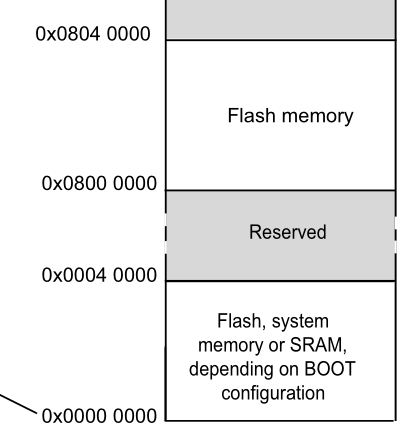
When we look at the photo in more detail, we can see that the Flash memory field is 0x8000000. Most of the Base Address of ARM-based processors is already at this address, but if you still have a different board, it will be useful to look at the address with the datasheet.
Then let’s write the address we obtained with the datasheet in the Base Address field from Ghidra’s Options tab:
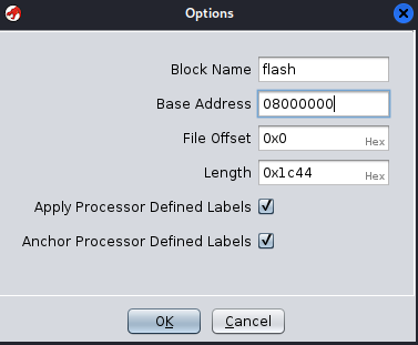
I gave the Block Name as flash, you can do the same. We don’t need to touch other settings, we just need to give Block Name and Base Address values. Click the OK button and double click on the .bin file on the screen.
But we will need to make a few more settings. When the CodeBrowser screen opens, click on the Memory Map section in the middle of the screen:
Then click on the ‘+’ sign at the top right of this screen:
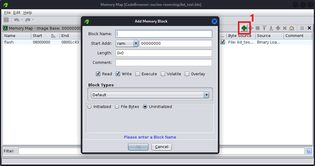
Again, we will need to set a few memory areas here. First, we will need to set the Flash Memory area. So what is this? Flash Mirror represents the area where the executable code of the firmware is usually stored. In most embedded systems, this region starts at address 0x0 depending on the processor and is where the firmware will be loaded and executed. The Flash region contains the code region (e.g. main function, startup code, etc.)
We can still look at the datasheet to verify the offset. If we take a look again at the photo I shared above, we can see that it is in the 0x0 field for my board. Now let’s set this field:
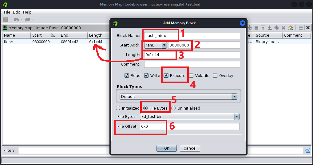
We can name the Block Name field ‘flash_mirror’. Then let’s give the Start Addr field at 0 by default. Set the Length field to be the same as the size of the field we set with the flash name as shown with the arrow. Then check the Execute box. In the Block Types field, check the File Bytes box and leave the File Offsett value at 0 and press OK to finish.
Let’s press the ‘+’ key again to set our last field. This time we will set the SRAM field. Generally its address is 0x20000000, but we can still check our board’s datasheet to verify this:
As you can see, it is located at address 0x20000000. Now let’s set the SRAM area:
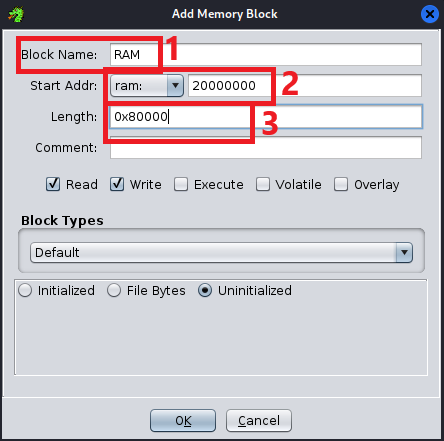
We can name the Block Name field as ‘RAM’. Let’s give the value 20000000 to the Start Addr field, and lastly give 80000 to the Length value. Then close the screen.
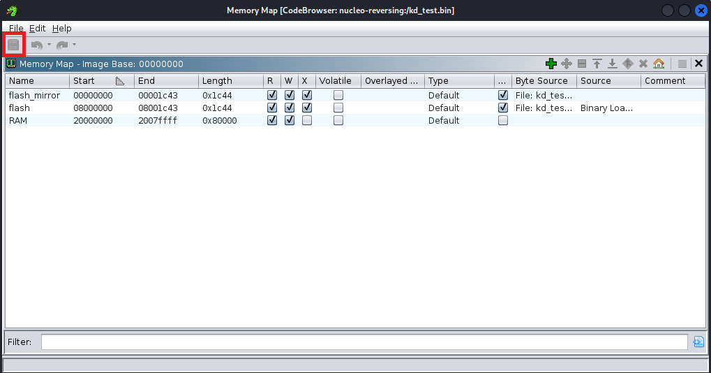
We are done. Now let’s press the save button at the top left of the screen and close the Memory Map screen:
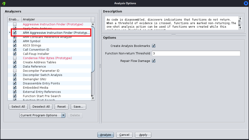
We have one last operation left. After closing the screen, go to Analysis > Auto Analyze’.bin’ from the bar on the top left of Ghidra and activate the ‘ARM Aggressive Instruction Finder (Prototype)’ option on this screen and click on the ‘Analyze’ button:
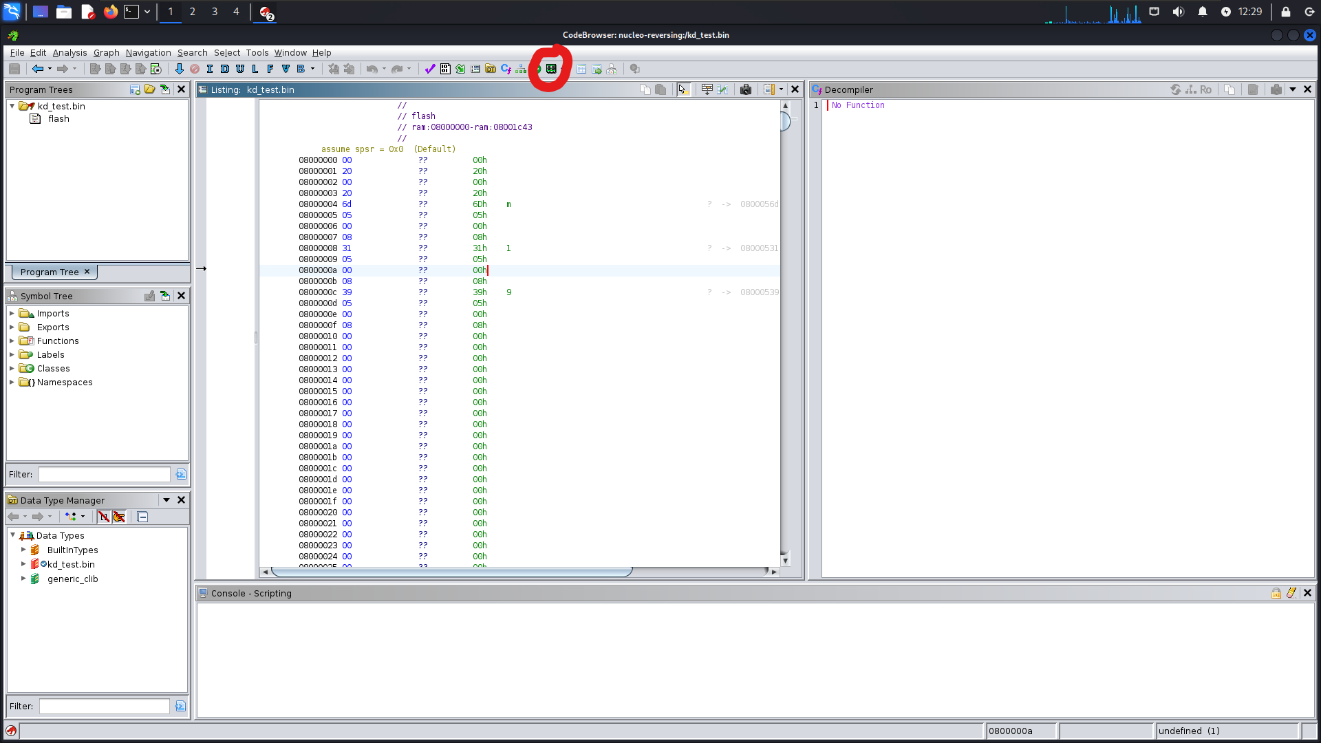
Now we are ready for everything. Now let’s take a look at the top side from the Disassembly screen:
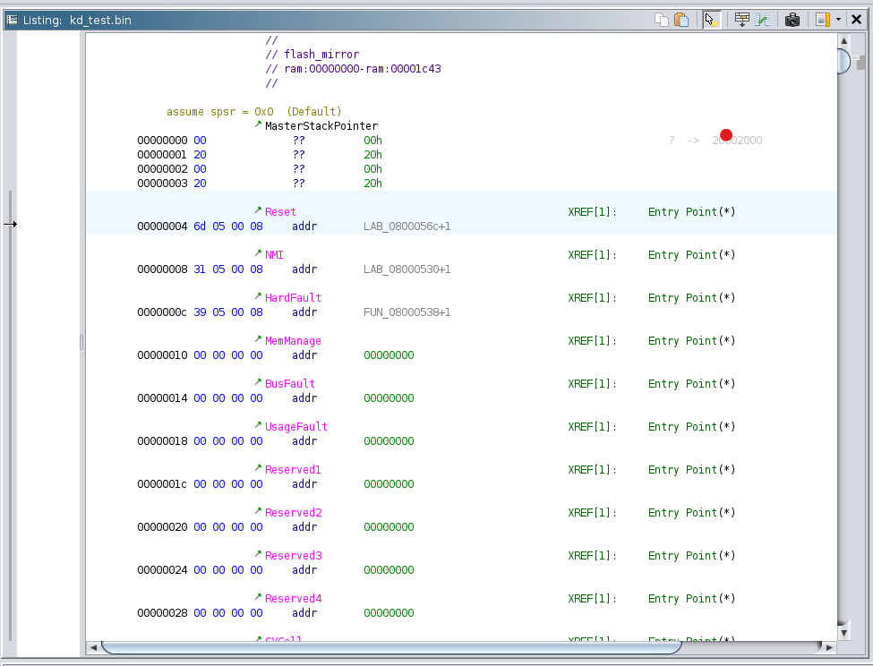
If you are new like me, you might be a bit confused when you see what is marked here, but it is actually simple. This area you see in the photo is called the ‘vector table’. This is where the CPU first loads the Stack Pointer when the system starts up. So the first address of the table is the starting address of the system’s stack memory. The processor then jumps to the Reset Handler address defined in this table.
The vector table defines how the microcontroller reacts to all interrupt and fault conditions that the microcontroller may encounter during operation. For example:
- Reset: Determines the address of the code that will run when the CPU is restarted. This is the initialization function that usually initializes the system.
- NMI (Non-Maskable Interrupt): An interrupt that cannot be masked, i.e. it must always be handled.
- HardFault: A handler that is called when a critical error occurs.
- BusFault: Handles hardware problems such as memory access errors.
- UsageFault: Provides handlers for software-related problems such as incorrect instructions or mathematical errors.
The part we will be interested in here will be the Reset field. The Reset vector contains simple setup codes, similar to the introduction section of the C Program. Since the main function is called in this vector, we will find the main function here.
Now double click on the address marked with the Reset vector:

Now let’s check the decompiler:
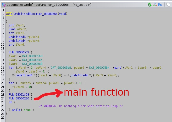
Here we see a few loops etc. being used and functions being called. I took a look at two of the three functions called but I didn’t understand anything and when I took a look at the last function called I confirmed that it was the main function:
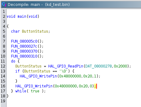
I updated the function names etc. to make it more understandable. When we look at the function, I already explained it when we were coding. There is no difference. Now we will return to Assembly codes and do Patch operation.
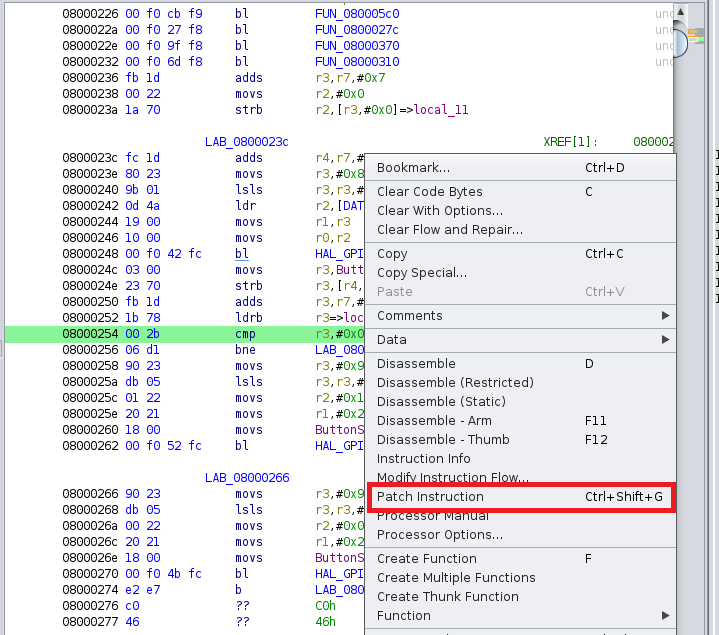
We will replace the ‘0’ value in the if condition with ‘1’. So the led will be on when we don’t press the button. Let’s find the instruction corresponding to the if condition in the Dissassembly screen of the main function and right click and select Patch Instruction:
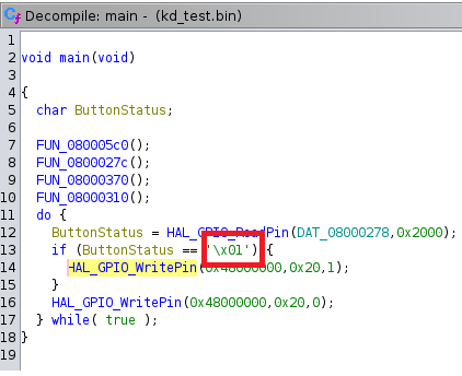
Then change 0x0 to 0x1 and press enter. After this process, when we check it from the Decompiler, the result should be as follows:
Now click on **File > Save ‘.bin’ As… at the top left of the Ghidra screen:
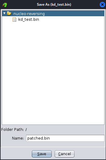
Save the project by giving it a name ending with ‘.bin’.
Finally, close the CodeBrowser screen and save the project:
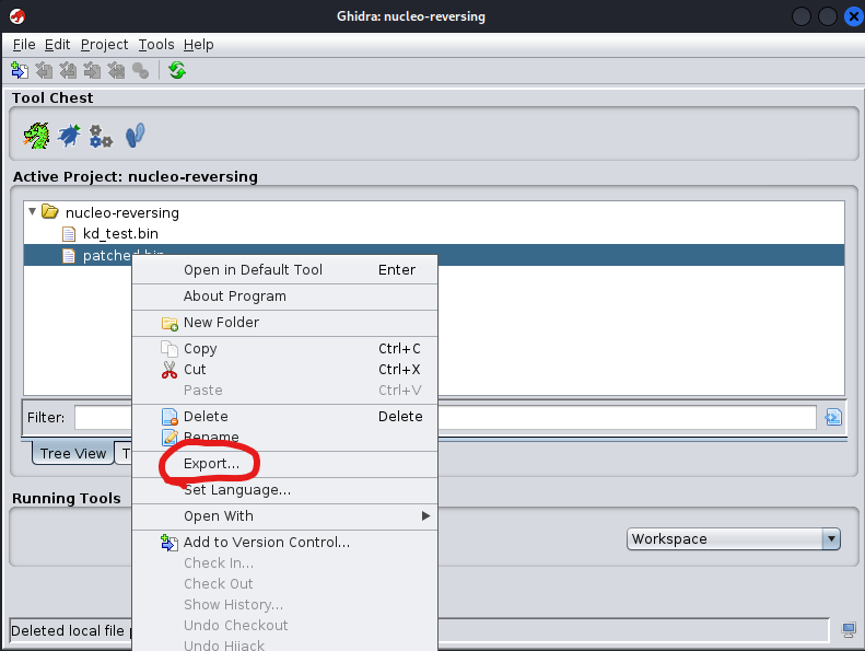
Now we will upload this reversed .bin file to our board via CubeProgrammer.
Let’s start CubeProgrammer and connect our board with the Connect button on the top right of the program:
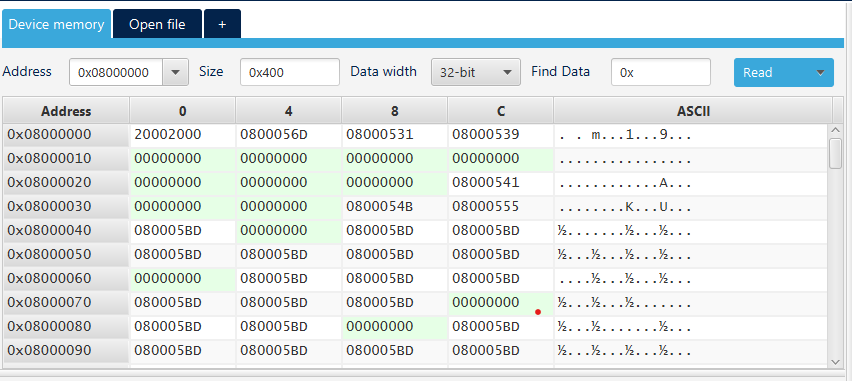
As you can see, we see the memory addresses etc. when connected to our board.
Let’s select the .bin file that we have reversed by clicking on the ‘Open File’ option in the program and then click on the ‘Download’ option to upload the firmware we have reversed to our card:
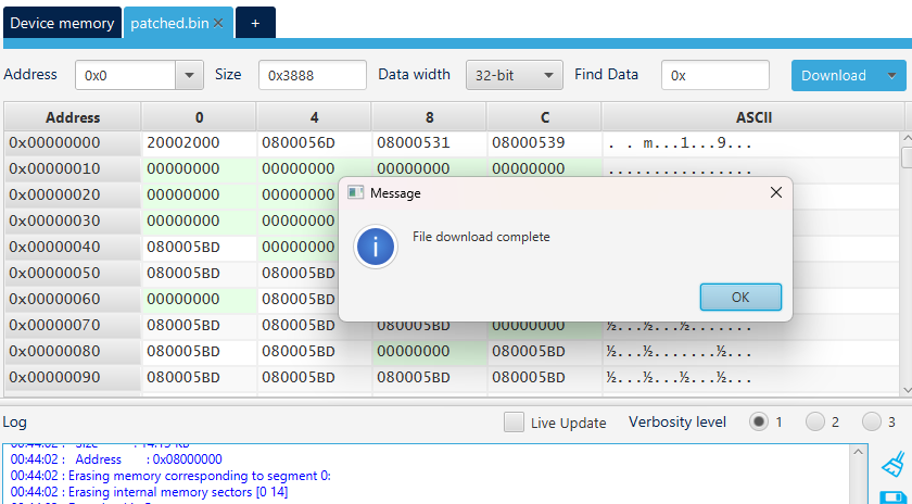
As you can see, we get the message ‘File Download Complete’ on the screen.
The Result
As it can be seen from the video, the Led lights up when we do not press the Button. If we press the button, the led goes out.
Basically what we did was quite simple. We simply coded our card to turn on the led when the button is pressed, and we reversed the firmware of the card with Ghidra and adjusted it to do the opposite of what we coded and reinstalled it on the card.
I hope the content was useful for you. If you want to investigate the subject in more detail, you can take a look at the resources I left as a reference.