Introduction to UEFI
Hello everyone. In this first document of UEFI Development, we will introduce the theory behind UEFI.
What is UEFI?
UEFI (Unified Extensible Firmware Interface) is a specification for a computer’s firmware. When the power button of a computer is pressed, UEFI runs before the operating system is started.
We can think of UEFI as an improved version of the old BIOS system. UEFI models also have basic I/O systems for interacting with hardware, but the system boot processes are different. UEFI uses GPT (Guid Partition Table). GPT is a modern standard that defines the layout of partitions on a computer’s storage device. It is the standard used in devices such as HDDs or SSDs that we are all familiar with. Just as UEFI replaced BIOS, GPT has replaced the previously used MBR (Master Boot Record) partitioning table. GPT works seamlessly with UEFI.
The advantages gained when combining UEFI and GPT are as follows:
- Support for 2TB or larger disks
- Faster booting process
- Simplified development compared to the old BIOS
So we can see that UEFI and GPT offer more advantages than older systems.
UEFI has the same tasks as BIOS: running I/O devices and transferring control to the OS. However, its task is not limited to this, and as I mentioned above, it also offers a wide range of options for pre-OS development.
Let’s take a look at the diagram below, which shows the difference between Legacy BIOS and UEFI:
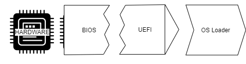
When we look at the diagram, we see that BIOS is firmware that communicates directly with hardware and is also hardware itself. When we look at UEFI in the diagram, we can see that it combines the interface between the hardware and the operating system. This function of UEFI makes things easier for developers.
In short, when we look at UEFI, we can see that it offers a more modern and faster process compared to the old Legacy BIOS, especially when used with GPT.
UEFI Boot Process
Let’s take a closer look at what happens in the background after pressing the power button on a UEFI computer, before the logo appears.
UEFI has six main boot stages that are critical to the platform’s startup process:
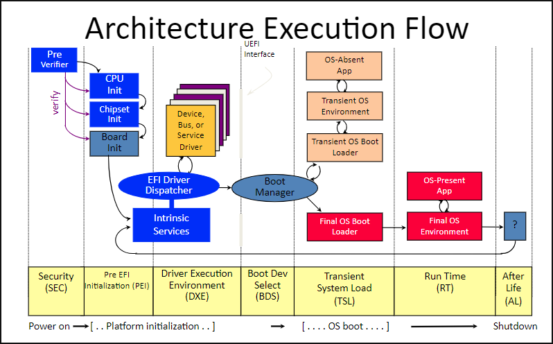
- Security (SEC): The Security phase is the first stage of the UEFI boot process. Its main purpose is to initialize the Temporary RAM store, act as the system’s root of trust, and provide information to the Pre-EFI core phase. The mentioned root of trust works as follows: the SEC mechanism also serves as a system that ensures any code executed in the PI (Platform Initialization) is digitally signed, creating a Secure Boot environment.
- Pre-EFI Initialization (PEI): In the second stage, the execution of EFI code is enabled. Its primary responsibility is to load the DXE Foundation, which will initiate the DXE drivers in the next stage. It also uses processor resources to dispatch Pre-EFI Initialization Modules (PEIMs). These PEIMs handle critical processes such as initializing certain persistent memory components and ensuring the transition to the next stage — the Driver Execution Environment (DXE).
- Driver Execution Environment (DXE): I think this stage is particularly important because major operations required to start the system occur here. In the PEI stage, the memory needed for DXE to operate is allocated and initialized. Once control is passed to DXE, the DXE Dispatcher is called. This Dispatcher is responsible for loading and executing hardware drivers, runtime services, and all boot services required for the operating system to start. In the context of our goal, as I mentioned earlier, this is a crucial stage — our driver will be executed here.
- Boot Device Selection (BDS): After the DXE drivers have been executed, control is passed to BDS — likely the stage you’ve all seen before. Here, a selection is made as to which device the OS loader will be sought from. The operating system is then prepared for loading, and the process moves toward the Transient System Load (TSL) stage.
- Transient System Load (TSL): At this stage, the selected boot loader runs, and UEFI boot services are terminated.
- Runtime (RT): In this phase, the UEFI flow is handed over to the operating system. However, this does not mean UEFI disappears entirely. The Runtime Services belonging to UEFI remain available to support the OS. For hardware-specific tasks, the System Management Mode (SMM) comes into play. SMM is a secure mode in which the processor manages critical hardware functions independently of the operating system. For example, tasks such as adjusting fan speed or monitoring battery status are performed in this mode. If the OS cannot perform a certain hardware-related operation on its own, it sends a signal called SMI (System Management Interrupt) — essentially a “call for help.” For instance, when the OS wants to control fan speed, it sends an SMI, SMM kicks in, and the task is handled there.
Introduction to UEFI Development
When it comes to sources for UEFI development, you’ll really see that resources are limited. Popularly, the following tools can be used during the development process.
- EDK2: EDK2 is a toolset for UEFI and PI specifications with modern features like rich, cross‑platform coding. The EDK2 project is developed and maintained today by many of the developers who contribute to the UEFI specification (along with community volunteers).
In this series, we’ll use it for coding. Since EDK2 includes the latest UEFI protocols, it’s extremely useful. In addition, there are many projects we can use as guides during the learning process.-
- VisualUEFI: The VisualUEFI tool enables Windows users to develop EDK2 projects with the Visual Studio IDE. If you want to escape EDK2’s complex layout and work more comfortably, you can opt for this tool.
Although I’m a Windows user, I won’t be using VisualUEFI in the serie. While VisualUEFI provides a comfortable environment for coding, I personally find it easier to manually work with project layouts like EDK2. If you want to install VisualUEFI, there are plenty of resources online.
After we develop our projects, we’ll need to simulate them. One of the following can be used:
- QEMU: You probably already know what QEMU is. Being an emulator rather than just a virtual machine, it offers good debugging capabilities and is a multi‑platform emulator. You can choose it in either Linux or Windows environments.
- VMware / VirtualBox: You can also use virtual machines such as VMware or VirtualBox.
Setup EDK2 on Windows
Before setting up the EDK2 project in Windows, we need to install the following tools:
- Git
- Python
- NASM
- Visual Studio
First, let’s download Git, and then Python. Download Python directly from the original website instead of the Microsoft Store, and pay attention to the following during installation:
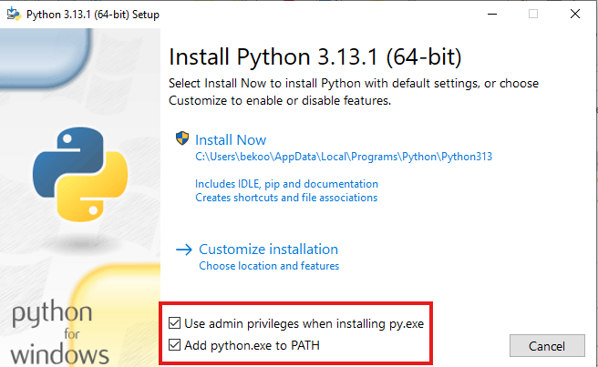
Don’t forget to check the boxes in the area shown in the photo.
Next, download NASM from its original website and run the downloaded .exe file as an administrator:
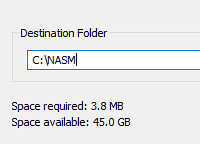
During installation, set the location of the NASM project to C:\NASM.
After installing NASM, create a variable named NASM_PREFIX for User Variables in Windows’ Environment Variables settings:
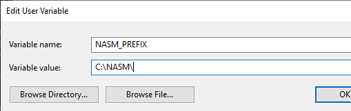
Let’s set the value to C:\NASM.
Next, we need to install Visual Studio’s C++ tools. To download these tools, search for Build Tools on the Downloads page:
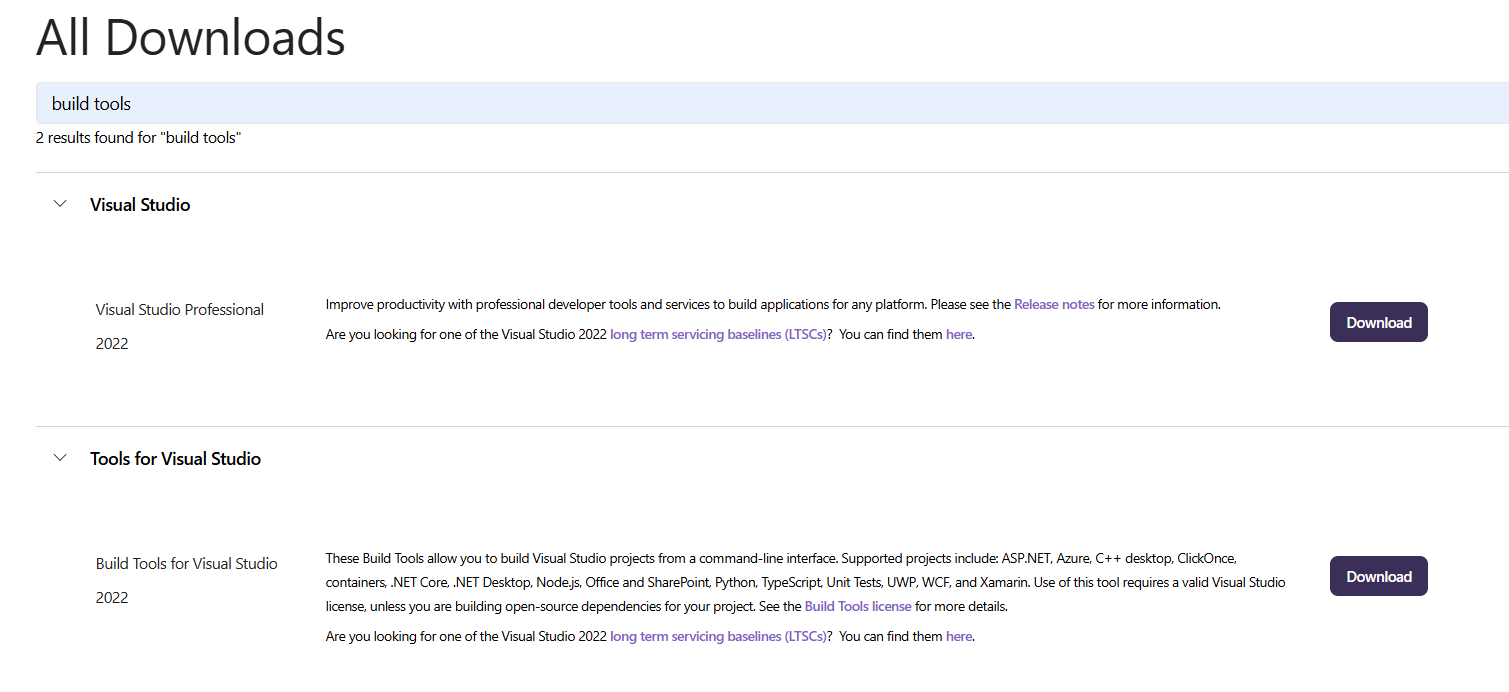
Let’s download Tools for Visual Studio and then:
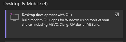
Select Desktop Development with C++ during installation and start the installation.
Once you have completed these steps, open cmd.exe and install the edk2 project:
git clone https://github.com/tianocore/edk2.git
cd edk2
git submodule update --init
After downloading the edk2 project, open the Developer Command Prompt VS 2022 tool and then go to the edk2 project we downloaded. Open Config/target.txt with Notepad:
notepad Conf\target.txtIn this .txt file, replace the values with the ones I show you below:
ACTIVE_PLATFORM       = ShellPkg/ShellPkg.dsc
...
TARGET                = RELEASE
...
TARGET_ARCH           = X64
...
TOOL_CHAIN_TAG        = VS2022
Change the values accordingly and save and close. Then run edksetup.bat:
> C:\edk2>edksetup.bat
...

 WORKSPACE      = C:\edk2
 EDK_TOOLS_PATH      = C:\edk2\BaseTools
 BASE_TOOLS_PATH     = C:\edk2\BaseTools
 EDK_TOOLS_BIN      = C:\edk2\BaseTools\Bin\Win32
 CONF_PATH      = C:\edk2\Conf
 PYTHON_COMMAND = py -3
 PYTHONPATH = C:\edk2\BaseTools\Source\Python;


!!! WARNING !!! NASM_PREFIX environment variable is not set
  Found nasm.exe, setting the environment variable to C:\nasm\

!!! WARNING !!! CLANG_BIN environment variable is not set

!!! WARNING !!! No CYGWIN_HOME set, gcc build may not be used !!!
Next, let’s go to the BaseTools directory to compile the tools:
> C:\edk2>cd BaseTools

> C:\edk2\BaseTools>nmake
After compiling the tools, let’s return to the main directory and run the Build command:
> C:\edk2\BaseTools>cd ..

> C:\edk2>Build
...

- Done -
Build end time: 13:14:44, Jan.28 2025
Build total time: 00:02:03
Hello World with UEFI
We now have everything we need to develop a UEFI driver. Let’s develop a simple project that outputs “Hello UEFI World”. We can create the projects we will develop under the ShellPkg/Application directory.
When developing a driver, in addition to a .c project, we also need to create an .inf file. This INF file provides the necessary information to create and package the module. In other words, we will provide the necessary information for packaging our driver.
Let’s create a folder named HelloWorld under the edk2/ShellPkg/Application directory and then start coding our HelloWorld.c project:
#include <Uefi.h>
#include <Library/UefiApplicationEntryPoint.h>
#include <Library/UefiLib.h>
#include <Library/PcdLib.h>

EFI_STATUS
EFIAPI
UefiMain (
  IN EFI_HANDLE        ImageHandle,
  IN EFI_SYSTEM_TABLE  *SystemTable
  )
{
  Print (L"Hello UEFI World!\n");
  return EFI_SUCCESS;
}
Aside from some details, the code will not seem foreign to us.
For the main function, we will write our code inside UefiMain. UefiMain is the entry point of UEFI drivers. Similar to the traditional main function, it is the entry point of a UEFI application. UefiMain takes two parameters:
- ImageHandle: A unique identifier for the application, represented by the UEFI firmware.
- SystemTable: A data structure providing access to various services and tables defined in the UEFI system.
When you look at the code more closely, you might have felt your hands shake a bit because of the syntax differences (for example, the space left between Print and the parentheses). At first, like me, you might think this is a syntax error — but it’s not. It’s related to the C coding style used by the EDK2 community:
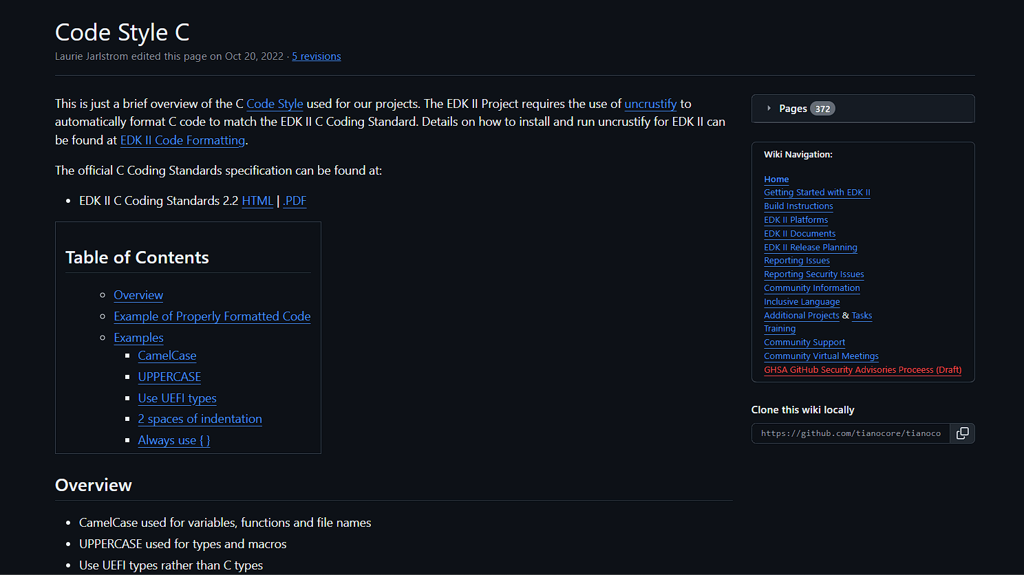
Then let’s create another project called HelloWorld.inf:
[Defines]
  INF_VERSION                    = 0x00010006
  BASE_NAME                      = HelloWorld
  MODULE_TYPE                    = UEFI_APPLICATION
  VERSION_STRING                 = 1.0
  ENTRY_POINT                    = UefiMain

[Sources]
  HelloWorld.c

[Packages]
  MdePkg/MdePkg.dec
  ShellPkg/ShellPkg.dec
  MdeModulePkg/MdeModulePkg.dec

[LibraryClasses]
  UefiApplicationEntryPoint
  UefiLib
  PcdLib
After coding the .inf file, everything is complete, but before moving on to compilation, we will need to add our project to /edk2/ShellPkg/ShellPkg.dsc:
...
[Components]
  #
  # Build all the libraries when building this package.
  # This helps developers test changes and how they affect the package.
  #
  ShellPkg/Library/UefiShellLib/UefiShellLib.inf
  ShellPkg/Library/UefiShellAcpiViewCommandLib/UefiShellAcpiViewCommandLib.inf
  ShellPkg/Library/UefiShellCommandLib/UefiShellCommandLib.inf
  ShellPkg/Library/UefiShellCEntryLib/UefiShellCEntryLib.inf
  ShellPkg/Library/UefiHandleParsingLib/UefiHandleParsingLib.inf
  ShellPkg/Library/UefiShellBcfgCommandLib/UefiShellBcfgCommandLib.inf
  ShellPkg/Library/UefiShellLevel1CommandsLib/UefiShellLevel1CommandsLib.inf
  ShellPkg/Library/UefiShellLevel2CommandsLib/UefiShellLevel2CommandsLib.inf
  ShellPkg/Library/UefiShellLevel3CommandsLib/UefiShellLevel3CommandsLib.inf
  ShellPkg/Library/UefiShellDriver1CommandsLib/UefiShellDriver1CommandsLib.inf
  ShellPkg/Library/UefiShellInstall1CommandsLib/UefiShellInstall1CommandsLib.inf
  ShellPkg/Library/UefiShellDebug1CommandsLib/UefiShellDebug1CommandsLib.inf
  ShellPkg/Library/UefiShellNetwork1CommandsLib/UefiShellNetwork1CommandsLib.inf
  ShellPkg/Library/UefiShellNetwork2CommandsLib/UefiShellNetwork2CommandsLib.inf
  ShellPkg/Application/HelloWorld/HelloWorld.inf
As shown above, add your HelloWorld project under Components.
Now let’s compile our project:
Build -m ShellPkg\Application\HelloWorld\HelloWorld.infRunning the Driver
I will be using the VMWare environment for simulation operations. If you are using VMware or VirtualBox like me, you will need a USB flash drive formatted with FAT32. After formatting with FAT32, create a directory named efi/boot on the USB flash drive.
There will be two shell files under the /edk2/Build/Shell/RELEASE_VS2022/X64 directory:
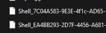
Copy any of these to the efi/boot directory as bootx64.efi. Then copy the HelloWorld.efi file to the root directory.
After these steps, the contents of the USB flash drive should be as follows:
-
- bootx64.efi
Let’s start the virtual machine and perform the following steps:
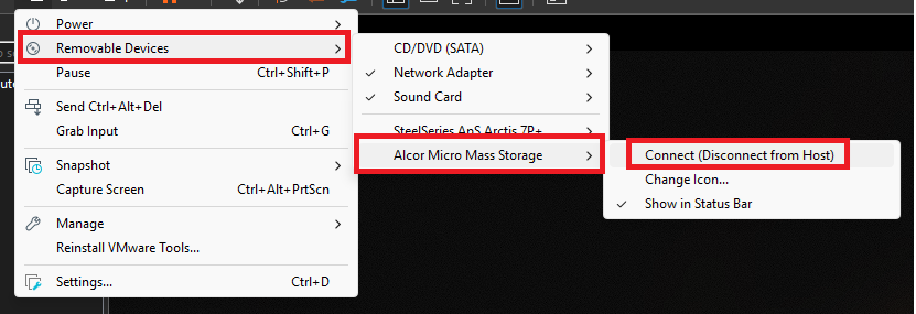
Removable Devices > USB Flash Drive > Click on the Connect option.
Restart the virtual machine and press the DEL key at startup:
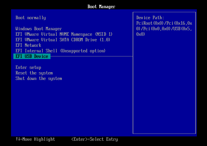
Select your USB flash drive from the Boot Manager screen. It’s that simple!
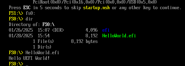
Now let’s run our HelloWorld driver:
Conclusion
In this first chapter of UEFI development, we explored both the theory and the practical steps needed to start building UEFI applications. We learned that UEFI is a modern replacement for the traditional BIOS, offering faster boot times, support for large drives through GPT, and a more flexible platform for pre‑OS development. The six-stage boot process—from SEC to Runtime—provides a clear roadmap for how the system initializes, loads drivers, and eventually hands control to the operating system.